|
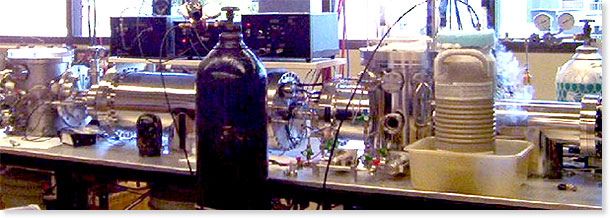
The MALDI-TOF Drift Cell Instrument, shown above, is used to investigate the conformational properties of small molecules, synthetic polymers and biomolecules in the gas phase. Sample preparation and instrumental details are explained below.
Sample Preparation. To prepare a sample for insertion into the MALDI-TOF Drift Cell Instrument, the compound of interest is dissolved (usually in methanol or tetrahydrofuran (THF)) to a concentration of 1 mg/mL. A matrix is then selected for its properties of laser energy absorption and solubility characteristics similar to those of the compound of interest. One of the most commonly used matrixes in our lab is 2,5-dihydroxybenzoic acid (DHB) dissolved to a concentration of 100 mg/mL in the same solvent as the compound of interest. Normally, 50 μL of the compound and 50 μL of the matrix solution are mixed together, so that the matrix-to-compound ratio is at least 100 to 1. The excess matrix allows the compound to be well shielded from the laser beam and avoid most fragmentation. To study neutral compounds, metal cations are added by mixing approximately 8 μL of a saturated salt solution with the 100 μL compound/matrix mixture. The final solution is then applied to a 2.8 cm section of a stainless steel cylindrical rod (1.27 cm in diameter) and dried.
MALDI Source. The rod containing the dried sample is inserted into the MALDI source and a stepper motor rotates and translates the stainless steel rod, exposing fresh areas of sample to the laser. A nitrogen laser (Lasertechnik Berlin MSG 400, λ=337 nm) with a pulse width of ≤10 ns is used to desorb and ionize the sample. The laser is usually operated at 20 Hz and has a maximum average power of 12 mW. The ions are desorbed into a two-section (Wiley-McLaren) ion source and accelerated down a 1 meter long flight tube with a pulsed 9 kV acceleration voltage.
Mass Spectrometric & Ion Mobility Analysis. To obtain high-resolution mass spectra of the ions formed in the source, the reflectron in the TOF analyzer region is turned on and the ions are detected by a microchannel plate. An illustration depicting this mode of operation can be seen by clicking on the button labeled Detector 1 in the figure below.
For the ion mobility experiments, the reflectron is turned off and a linear mass gate is turned on, allowing the ions to travel through to the drift cell. In order to prevent collision-induced dissociation, the ions are decelerated to less than 100 eV before they are focused into the 0.5 mm entrance orifice of the drift cell. The 20 cm long cylindrical glass drift cell is filled with ~1.5 Torr of helium gas. Twenty drift guard rings are spaced evenly throughout the cell to provide a uniform electric field across the cell. The cell temperature is most often kept at 300 K for initial experiments, but can be varied from 80 to 500 K depending on experimental needs. In the drift cell, ions are separated based on their mobility. Click on the Drift Cell button in the figure below for an illustration of this process. After exiting the drift cell through another 0.5 mm orifice, the ions are gently accelerated through a quadrupole mass filter and detected with an electron multiplier. The quadrupole is set to a specific mass-to-charge ratio (m/z) to eliminate any ions that might arise from fragmentation in the drift cell and interfere with mobility measurements. The pulsed source extraction voltage triggers a timing sequence so that the ions are detected as a function of time, yielding an arrival time distribution (ATD). Click on the button labeled Detector 2 below for an illustration. The ATD is collected on a multi-channel scalar with a 5 μs time resolution. From a series of ATDs measured at different voltages across the drift cell (7.5–16 V/cm), the reduced mobility, Ko, of the ions is accurately determined and using kinetic theory, the ion’s collision cross section can be calculated.
|